

Search keywords:
product name, product type, model number,
test method, manufacturer, technique, application
-
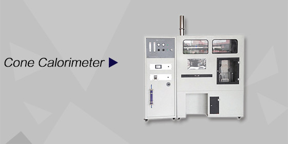
Cone Calorimeter
The import of American VTEC, cone calorimeter ultra high cost performance
more
-

Digital Elmendorf Tearing Tester
Pendulum method test material tear strength, operating more simple, more accurate data
more
-
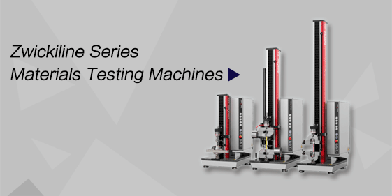
ZwickiLine Materials testing machines
Top of the world's leading universal material testing machine
more
Jet Fuel Filter Test Stands
BACK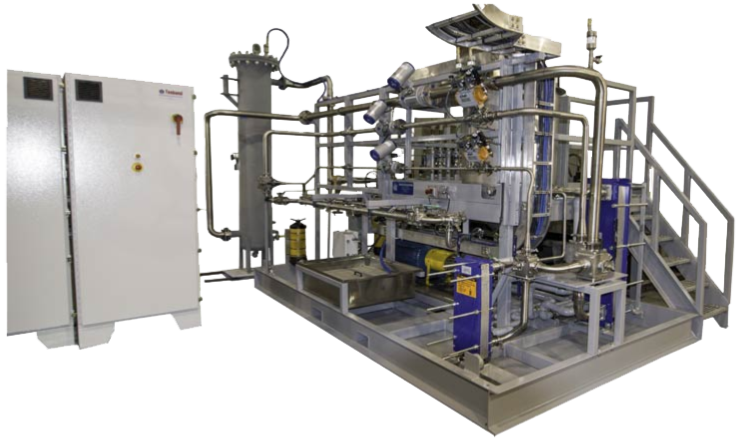
Standards:
SAE procedure ARP1827B
Applications:
Product Information:
The Jet Fuel Filer Test Stand performs dirt capacity testing of aircraft fuel filter elements as per SAE procedure ARP1827B. The fully automated system provides precisely controlled test conditions for accuracy, repeatability and operator safety.
Structures:
1. Main Circuit
The main fuel circuit provides a pressurized supply of the test fuel at the specified flow rates for burn flow and recirculated flow. Temperature of the fuel is maintained at 85±5℉ as specified by SAE ARP 1827B.
The elevated reservoir and contaminant belt feeder are accessible by platform. The pumping source is a low-flow, high-head pump with a radial vane impeller. The centrifugal-style pump was selected for its inherent mixing ability that facilitates contaminant suspension in the fluid. The pump is coupled to an electric motor with a variable-frequency drive. Supply pressure is modulated by the pump in concert with flow control valves as required to maintain constant flow through the test article as the contaminant loading changes. Fuel leaving the test article can be split into burn flow and recirculated flows to simulate the aircraft’s fuel system. Burn flow and recirculated flow circuits use flow control valves and ultrasonic flow meters to set and hold specified flow rates. The burn flow circuit is equipped with clean-up filters for removing contaminant, a fullers earth filter for adjusting fuel interfacial tension (IFT) and a coalescing filter for water separation. Manually-operated valves allow the operator to select the test station and the combination of burn flow and recirculated flow circuits desired. Two recirculated flow circuits accommodate the range of recirculated flow. Plate and frame heat exchangers remove heat from the fuel and transfer it to the customers cooling water system.
2. Test Station
The test station allocates a gap in the test circuit piping for installation of the test article. Sanitary tube flanges serve as the interface fittings for adaptation to the test article. Two test circuits are required to accommodate the range of flows. Each test circuit has upstream and downstream manual valves to isolate and select the flow paths required. Sample and vent valves allow draining prior to test article removal and installation. The sample valves also permit connection to a particle counter for side stream sampling.
3. Water Injection Circuit
3. Water Injection Circuit
The influent water concentration and test flow is defined in the test procedure as 0.01 percent by volume. The software uses the target concentration and actual test flow to compute the needed water injection flow rate. Since this flow rate must be provided over a very wide range, a precision piston metering pump and variable speed controller are used for this purpose. The water used in the test is salt water in concentrations defined by MIL-E-5007D.
4. Pneumatic Supply Circuit
Compressed air is used for powering the control valves on the test stand. A separate compressed air circuit supplies dry purge air to the belt feeder enclosure.
5. Cooling Water Circuits
Two cooling water circuits remove pumping heat from the jet fuel to maintain a constant test fluid temperature. Each circuit contains a plate and frame style heat exchanger, an electro-pneumatic control valve and inlet/outlet thermometers. Facility cooling water is required for cooling the heat exchangers.
6. Electrical System
Two electrical cabinets are supplied, one for power distribution hardware and another for control equipment. These cabinets are not rated for placement in a hazardous area. Electrical power is delivered to the power cabinet at 480 volts AC, 3 phase. The 120 VAC power is distributed to the loads of the test stand through circuit breakers mounted in the power cabinet. Devices on the test stand that receive the 120V directly are explosion proof rated devices with wiring methods suitable for Class 1 Division 2 Hazardous area The circuit breakers prevent the various devices from overloading the circuit.
7. Emergency Stop Provision
E-Stop pushbuttons are located at the front panel and in explosion proof electrical boxes on the test stand at two locations in the Class I Division 2 hazardous area fed by suitable wiring and sealing fittings required for the Class I Division 2 location.
8. Control System
The host computer is a desktop personal computer (PC) with Windows 7.0 installed as the operating system. The computer system includes a laser printer.
National Instruments CompactDAQ distributed I/O hardware platform is Din rail mounted inside an enclosure located in the control room. An Ethernet cable connects the compacDAQ controller to the host computer. Application software for test stand data acquisition and control was developed using the National Instruments Labview development system.
National Instruments CompactDAQ distributed I/O hardware platform is Din rail mounted inside an enclosure located in the control room. An Ethernet cable connects the compacDAQ controller to the host computer. Application software for test stand data acquisition and control was developed using the National Instruments Labview development system.
